
In this post we'll cover new hardware additions to tonari and some of the work and research that went into powering that hardware. We're big fans of the Rust programming language but before this project we hadn't ever used it for embedded hardware. We'll go over our hardware requirements, some possible solutions, some reasons (excuses) for choosing Rust for the job, and provide a primer for getting into embedded programming with Rust. We'll end it with some photos of the absurd-looking hardware we created and our thoughts on doing all this work in Rust.
This article gets fairly technical with lots of acronyms and code snippets. We tried to spell out all the acronyms but let us know if we missed any!
If you want to skip straight to the code, you can find it here:
https://github.com/tonarino/panel-firmware
Motivations
Recently at tonari, we wanted to add a few new product features that give users and ourselves a bit more control over how we manage the environment around tonari. None of these features had a clear solution using our current hardware design, so we looked at this as an opportunity to think about how we might integrate new hardware and controllers into our system in the near-term and longer-term.
Volume control for shared audio
tonari users can share video and audio content — e.g. YouTube videos or screen mirroring — to both sides via a secondary 'share screen' next to the main tonari screen. We don't always have an easy way to optimize volume levels for this content, so we want to offer a simple and consistent way to increase or decrease the volume of shared audio, so that users on either side can find a comfortable balance between content and voices.
Quiet mode
Though tonari is always on, we completely acknowledge that sometimes people need privacy, or just some peace and quiet. I've been known to get a tiny bit loud when playing video games near tonari (or at least that's what the neighbors have told me). We want everyone to have the ability to easily enable a 'quiet mode' for this situation. The interface should be simple and accessible, so we prefer a physical hardware interface (such as buttons or dials) instead of a special app or complicated touch screen menus.
Dynamic lighting
Lighting conditions change throughout the day based on weather, time or day, or other things happening around tonari. Just like having a camera flash on a phone, having more control of the lighting can help us provide better image quality for both sides. So we want to have good overhead lighting above tonari, and be able to control the color temperature and brightness, to be able to adjust better to each environment and situation.
Summary of requirements
Based on the above features and motivations, we needed the following:
- Some sort of volume controller
- Interactive hardware, e.g. a button, to put tonari into 'quiet mode'
- Software control of the overhead lights
- The possibility to add more hardware components later as our needs grow
- Wired communication, for reliability and simplicity
Hardware selection
Volume hardware
Selecting hardware for volume control was fairly simple since there are only a few reasonable choices:
- Potentiometer — A variable resistor or voltage divider which changes resistance values as you rotate it
- Rotary encoder — If you've ever used a volume dial that you can spin forever, that was most likely a rotary encoder. They can give you absolute rotation values, or incremental values depending on the type. Their output is digital, whereas a potentiometer is analog.
- Up/down buttons
- Touch screen
We wanted the ability to reset the volume after a period of time so someone doesn't leave tonari in a muted state and confuse the next person who uses it. If we wanted to use a potentiometer with that restriction, it would need to be motor-controlled so we can reset it. These kinds of potentiometers are often seen on fancy audio equipment. We would need to include code to drive the motor appropriately and the price per-part is high compared to a simple potentiometer or rotary encoder.
Touch screens were immediately ruled out for being way too general-purpose and requiring much more code to implement.
Up/down buttons could work and be a very simple solution, but they're not very satisfying and are borderline annoying when you need to change the volume by a large margin.
That left us with rotary encoders. They're very inexpensive, fairly easy to write firmware to read from one, they can tell you which direction they're turning and roughly how fast, and some even come combined with a push button. They're not perfect, especially the cheaper ones which can have noise in the output, but for our uses they seemed like the right choice.
Lighting hardware
Lighting was a little less straightforward. All we knew was that we wanted control over brightness and color temperature, and ideally they could provide a high lumen output. "Smart" lighting like Phillips Hue was out of the question — they're more consumer oriented and typically require apps with a bluetooth or WiFi connection in order to control them.
Some brief research into this problem introduced me to DALI — Digital Addressable Lighting Interface. I read up on DALI for a few minutes and was convinced it was something we wanted to stay far away from. It's likely useful for huge networks of lights in warehouses or something like that, but for our situation where we're only controlling a few lights in the immediate area, it looked like extreme overkill.
Another complication is light flicker. Put simply, any sort of lighting flicker in a video is headache-inducing and unacceptable, especially at the wall-sizes tonari works at. We evaluated as many LED light bars as we could get our hands on, testing them on our camera setups at various frame rates. The funny thing about Japan is that their electrical system is split more or less down the middle: it's 60Hz in the west and 50Hz in the east.

We run our cameras at 60 FPS when we can but sometimes in the 50Hz region we have to drop to 50 FPS to remove light flicker from the existing light sources. Any light we select has to exhibit zero flicker at 50 and 60 FPS.
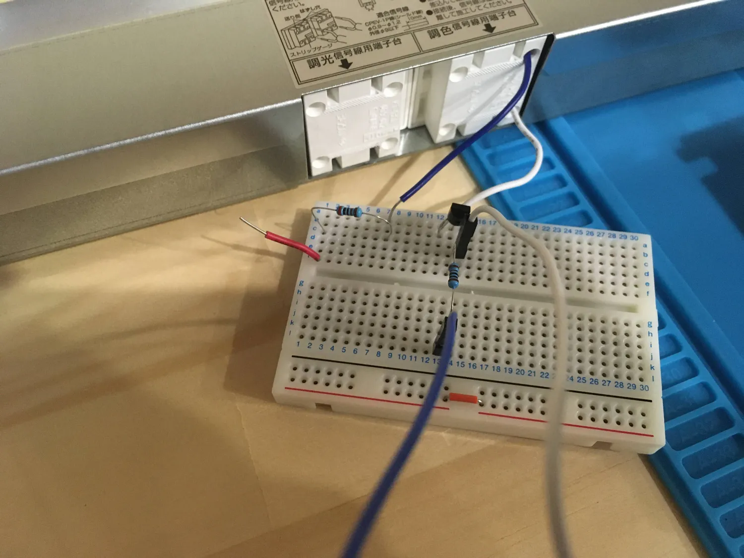
After our tests, we settled on Daiko LED light bars. They don't have flicker at the frame rates we run, they're affordable, bright, they support brightness and color temperature control, and their hardware control circuit seemed simple enough to plug in a custom controller.
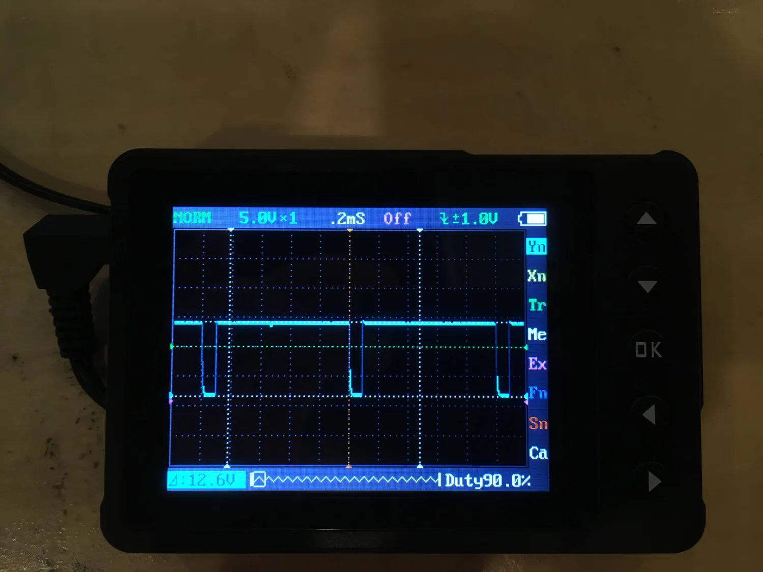
Their brightness and color temperature seemed to be completely controlled by PWM (pulse-width modulation) — it was written right on the dimmer panel. After a quick check of the provided dimmer with a multimeter and pocket oscilloscope, we learned that the PWM frequency was 1 KHz and the input voltage was +12V.
So to recap:
- We'll use a rotary encoder with pushbutton for volume control and extra user interactions
- Daiko LED light bars will be used
- We need a microcontroller which can interface with a rotary encoder and generate a 1 KHz PWM signal (pretty much any microcontroller can...)
Surveying of possible solutions
I personally have a small amount of microcontroller experience, mostly with the ESP8266 and ESP32, and a bit on the Arduino AVR boards. I was very close to just going with the ESP32 — I know it and it's packed with peripherals — WiFi, bluetooth, SPI, PWM, serial UART, etc. It's super cheap and widely available. I'm actually quite confident an ESP32 solution would have worked perfectly well, but I wanted to push myself a bit and learn something new. At least, that's what I tell myself, but in reality I wanted an excuse to try running Rust on an embedded platform.
As it turns out, there is significant progress being made on running Rust on the ESP32, so that will soon be an option. For now, the main way to run code on the ESP32 is through the official "esp-idf" (Espressif IoT Development Framework), using C.
I can write the ESP32 firmware in C and it'll get the job done, but it's not too fun to write when you know Rust. We already have an existing successful Rust codebase, so anyone who can work on that code can fairly easily jump over to working on Rust firmware. Having our main codebase and the firmware share languages means it will be easy to write a communication library that is shared between the two. The Rust compiler and its borrow-checking rules and type system means less errors at runtime such as configuring the wrong pins for a peripheral, initializing things in the wrong order, or trying to use a resource in two places at once. On top of that, learning new things in Rust is almost always fun and the compile times which would normally be somewhat painful are gone as embedded projects typically don't use the standard library or any heavy dependencies.
For embedded Rust today, the most popular microcontroller family seems to be the STM32 series by STMicroelectronics. I had ordered a few STM32 board variations several months prior on Aliexpress when I heard about them being recommended for Rust development.
I was still a little uncertain if this was the right path or if I was heading into a world of hurt so I experimented with the boards a bit. I began looking at some Rust documentation for one of the microcontroller families and ended up on their documentation, wondering what QEI stood for. It's Quadrature Encoder Interface, which is a type of rotary encoder, and happens to be the kind of encoder I purchased to experiment on! The STM32 chips have built-in hardware for decoding rotary encoders??? No way, that's too convenient. I wrote up a quick sample, connected the encoder to the correct pins on the microcontroller, and I was getting valid input from turning the dial, just like that. I was sold.
Getting started with embedded Rust
When I was researching the STM32, most people were recommending the "blue pill" board for Rust development. After a bit more reading, I heard most of those boards have an incorrect resistor value which can interfere with correct USB behavior. The "black pill" (who is naming these?) was recommended as an alternative which has the correct resistor value. I ordered that board, as well as a version which has a USB C connector (along with a better processor and more RAM, though I didn't know at the time).
Like most things from Aliexpress, they showed up several weeks later right when you forgot you ever ordered them. In the meantime I had begun collecting references from other Rust developers to help me get started:
- https://rust-embedded.github.io/book/
- https://josh.robsonchase.com/embedded-bootstrapping/
- https://n8henrie.com/2019/04/blinking-an-stm32-with-rust-from-macos/
I started with the STM32F411 board (the one with USB C) simply because USB C seemed kinda cool and modern on a microcontroller, though I ended up not using the USB connector much. You can get an idea of the various STM32 families on their site and on wikipedia. There is also a wonderful reference for getting started on the USB C "black pill" which you can find here:
https://therealprof.github.io/blog/usb-c-pill-part1/
Once I get a board, the first question I always have is "Okay, what are all the ways I can load code onto this, and how badly can I screw it up?". The answer, thankfully, is that the bootloader is burned into "system memory" (effectively read-only memory) at the factory and you can't just accidentally overwrite it. Depending on the particular microcontroller, there are various ways you can load code it. The STM32F411 supports programming over two different USARTs, USB DFU, and various I2C/SPI buses.
I had never used anything other than USB-UART programming on things like Arduino boards or of the ESP8266/ESP32 boards, so I started with that. ST-Link programming devices seem to be pretty popular for programming these boards as well, but I wanted to keep the hardware requirements fairly general to begin with, and I have plenty of USB-UART converter boards laying around. I used a SiLabs CP2102 serial converter and that was enough to begin flashing code (CP2102N is a faster, more modern version, by the way).
With USB-serial, the workflow goes something like this for most STM32 boards:
- Connect the UART's TX to pin A10, and RX to pin A9 (these pins change, depending on the chip and UART bus so reference the datasheet for your particular microcontroller)
- Connect GND to GND for both the serial converter and the STM32 board
- Optionally power the STM32 board from the serial converter if it has a 3.3V output, otherwise source 3.3V from somewhere else (make sure all the GND pins are connected!)
- Hold the BOOT0 button (bring BOOT0 voltage to ground), and press the Reset button. The built-in bootloader checks the status of BOOT0 at boot to determine what to do, if it's low it will be put into firmware upload mode.
- Use the
stm32flash - Ensure BOOT0 is held high (typically you'll just release the BOOT0 button, or move a 2-pin jumper to tie BOOT0 to your supply voltage)
- Press the Reset button again, the STM32 will now boot into your newly written firmware
Building the firmware
Of course, the above assumes you already have your firmware compiled and ready to be flashed. I won't go through all the gritty details in case this post goes out of date, but for now the documentation in the stm32f4xx-hal
Setting up an embedded Rust project isn't too different from a normal Rust project. Some main differences:
- You need to use
#![no_main]and#![no_std]at the top of your main source file - You need to specify a panic handler to define what your firmware should do if it encounters a panic.
panic-halt - A build target needs to be specified in a
.cargo/configfile. Example:
[target.thumbv7m-none-eabi]
rustflags = [
  "-C", "link-arg=-Tlink.x",
]

[build]
target = "thumbv7m-none-eabi"- The toolchain for this Rust target needs to be installed with the
rustup target add <TARGET>command
Once you have these things in place (and maybe copied some example code), you can build the firmware with the normal cargo build routine. One more step is needed before you can flash this output though. cargo build will produce an ELF executable for most embedded targets, but we want to remove the extra headers and such that come with ELF so we just have the raw ARM executable instructions. We can accomplish this with cargo-binutils:
cargo install cargo-binutilsrustup component add llvm-tools-preview
Then, running cargo objcopy --release -- -O binary my-firmware.bin will give you a neat and tidy my-firmware.bin file ready to be uploaded to the microcontroller with an invocation of stm32flash.
Wrapping our heads around all the ecosystem pieces
The Rust embedded ecosystem is quite a bit different than the desktop ecosystem. There are more layers involved, and you have to understand at least a little bit about the hardware to know how the pieces fit together.
Most microcontrollers are composed of two major parts: the microprocesso (such as an ARM Cortex M0) and "hardware peripherals". The microprocessor, or core, carries out firmware instructions, does calculations, and reads and writes to and from RAM. The hardware peripherals vary from one microcontroller to the other, and they're a large deciding factor in which controller to use for a project. Some examples of hardware peripherals:
- GPIO — General Purpose Input/Output. Set a pin to output logically high or low voltages, or read a digital input signal
- PWM — Pulse Width Modulation. "Pulses" a digital signal at a certain frequency and duration. Useful for motor and servo control, fading LEDs smoothly, or emulating an analog output.
- UART — Universal Asynchronous Receiver Transmitter. Communicate with other controllers or computers over two wires
- I2C — Inter-Integrated Circuit. Another communication protocol used commonly to communicate with sensors
- ADC — Analog to Digital Converter. Convert analog voltages to a digital value. For example, a voltage anywhere from 0 to 5 volts could map to the digital numbers 0 to 1024.
- DAC — Digital to Analog Converter. Like the ADC, but in the opposite direction.
- Timers — Keep track of time, schedule events to fire at specific times, etc.
- USB, Ethernet, WiFi, Bluetooth — Communicate over various wired and wireless protocols to interact with common consumer devices.
Memory-mapped Registers
Many microcontrollers, especially embedded ARM systems, interact with hardware peripherals via memory-mapped registers. These are simply particular locations in memory which you can read and write from in order to control a peripheral. A given microcontroller can have hundreds of registers for its hardware peripherals, so it's not really sustainable to manually refer to memory locations to read and write from every time you want to interact with hardware.
This is all explained nicely in the embedded book but I'll summarize here as well.
Layer 1: Peripheral Access Crates
There are what are called "Peripheral Access Crates" (PAC) which have structs defined for each peripheral, and allow you to read and write register values in a type-safe way. These crates are often auto-generated. In the case of ARM microcontrollers, this is typically done with the svd2rust
An SVD file (System View Description) lays out a microprocessor and all its hardware peripherals in (hopefully) exact detail down to what each bit in a register controls. This level of detail allows svd2rust to generate structs and methods which act on those structs to read/write registers, which in turn allows us to control the hardware peripherals.
Here's an example from the stm32f4
use stm32f4::stm32f401;

let mut peripherals = stm32f401::Peripherals::take().unwrap();
let gpioa = &peripherals.GPIOA;
gpioa.odr.modify(|_, w| w.odr0().set_bit());
This code sets the bit at location 0 to 1 in the ODR (Output Data Register) of GPIO bank A. Assuming proper initialization of GPIOA, this will set the output of pin A0 high. Notice also that you have to make a call to Peripherals::take() to gain ownership of the peripherals. This uses Rust's borrowing rules so we don't have multiple pieces of code trying to access peripherals at the same time, and it's a common pattern in embedded Rust.
Layer 2: HAL crates
You can see how this sort of operation can be abstracted further, and that's exactly what HAL crates (Hardware Abstraction Layer) do! For example, I started with the stm32f4xx-halA0 high:
// pac = Peripheral Access Crate
let device_peripherals = pac::Peripherals::take().expect("failed to get stm32 peripherals");
let gpioa = device_peripherals.GPIOA.split();
let mut led = gpioa.pa0.into_push_pull_output();
led.set_high().unwrap();
On top of providing an easier interface to work with the hardware peripherals of a particular microcontroller, HAL crates also implement traits from the embedded-hal
For example, if you have a temperature sensor you interact with via I2C, you can write a driver for that sensor with embedded-hal which will work with all microcontrollers which implement the HAL traits. Make your driver generic over the I2C traits defined in embedded-hal and you're good to go! At least, that's the dream, it's still in development so there are probably still paper cuts but it's a brilliant idea that can bring huge time savings to embedded development.
Layer 3: Board crates
One level above HAL crates are the board crates. These are targeted at a specific board (a fully assembled PCB with particular pin wirings and component connections) to make it even easier to program.
For example, the Adafruit Feather STM32F405 Express has a board support package.
You'll notice from the product page that this board has an SD card slot on the bottom, a NeoPixel (RGB LED), and a red indicator LED near the USB port.
Here is the board support package (board crate): https://crates.io/crates/feather-f405
The crate has specific support for the NeoPixel, SD card slot, and indicator LED. These boards and crates are typically the easiest way to get started on embedded Rust systems as the component wirings have all been predetermined and encoded in the type system for immediate use. Board support crates are more rare though and it can restrict you in terms of hardware selection and functionality unless everything you want is implemented.
Firmware architecture
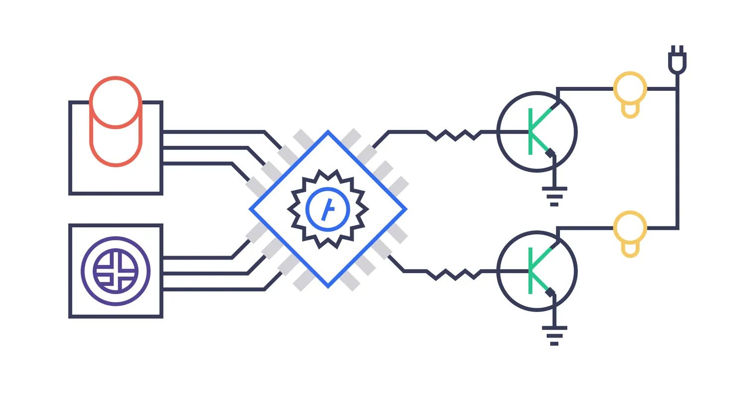
Our firmware requirements are pretty simple, here is an overview of its responsibilities:
- Poll the push button on the rotary encoder to see if a user has pressed it or long-pressed it, and report that to the computer powering tonari
- Poll the rotary encoder to see if the user has rotated it, and report the number of "ticks" they've rotated it
- Poll the serial port to see if the tonari binary has sent us any commands to execute, such as changing the brightness of the lights
None of these tasks are particularly time consuming or require very precise timing, so we opted to stay at the HAL crate level, using the stm32f4xx-hal crate. Here is literally the main loop of our firmware:
loop {
    match encoder_button.poll() {
        Some(ButtonEvent::Pressed) => {},
        Some(ButtonEvent::ShortRelease) => {
            protocol.report(Report::Press).unwrap();
        },
        Some(ButtonEvent::LongPress) => {
            protocol.report(Report::LongPress).unwrap();
        },
        Some(ButtonEvent::LongRelease) => {},
        _ => {},
    }

    if let Some(diff) = counter.poll() {
        if !encoder_button.is_pressed() {
            protocol.report(Report::DialValue { diff }).unwrap();
        }
    }

    match protocol.poll().unwrap() {
        Some(Command::Brightness { target, value }) => match target {
            0 => front_light.set_brightness(value),
            1 => back_light.set_brightness(value),
            _ => {},
        },
        Some(Command::Temperature { target, value }) => match target {
            0 => front_light.set_color_temperature(value),
            1 => back_light.set_color_temperature(value),
            _ => {},
        },
        _ => {},
    }
}
Here it is in our codebase.
Pretty readable, right? Rust has allowed us to create abstractions which control low-level hardware and at the same time write approachable and easily-changeable firmware. Whenever we added new components, we tried to make them generic over the embedded-hal traits.
Our button logic is generic over embedded-hal's InputPin trait (source here)
pub struct Button<T: InputPin> {
    pin: Debouncer<T>,
    ...other state
}

pub struct Debouncer<T: InputPin> {
    pin: T,
    ...other state
}
So we can take any GPIO pin, and provided it acts as an input pin, we can created a debounced button which can detect presses and long presses. You can read a bit about button debouncing here.
The overhead light structs are similarly generic over embedded-hal PWM channels. embedded-hal conveniently has a trait for QEI (Quadrature Encoder Interface) so we were able to use that for the rotary encoder.
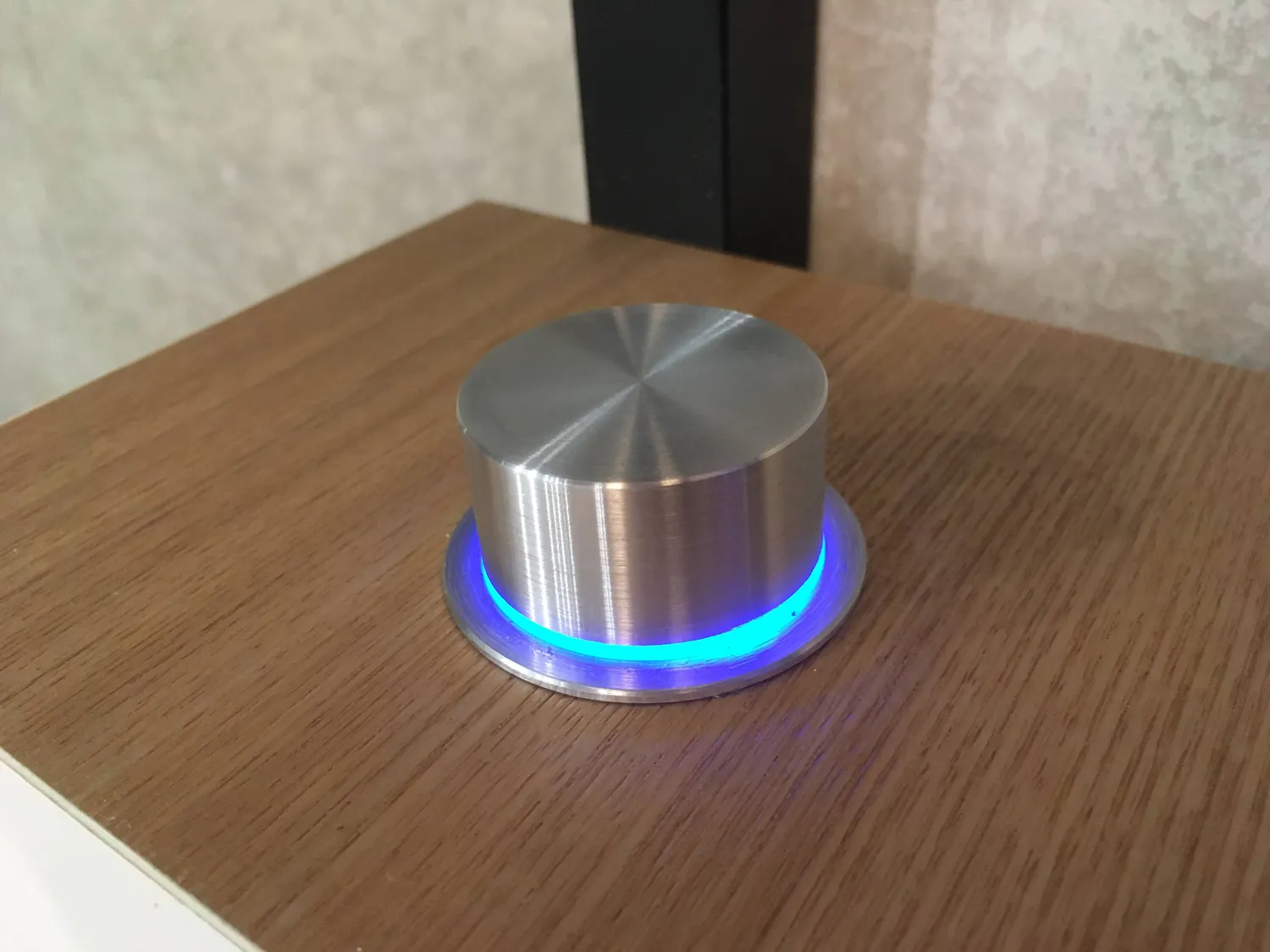
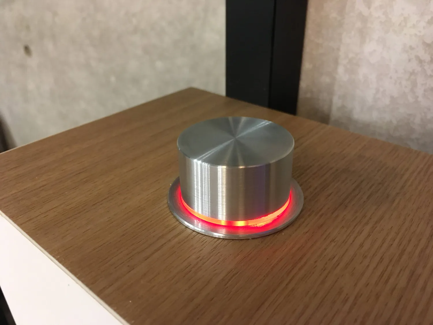
A small feature addition
A requirement came up later in the project: we wanted to illuminate the underside of the rotary encoder with an RGB LED which could potentially indicate the status of tonari in some situations.
The most popular LED to reach for when you need multi-color output is a NeoPixel, or WS2812B LED. These do require fairly specific timing, but most people have a lot of success in hacking the SPI (Serial Peripheral Interface) bus found on many microcontrollers to drive this. SPI is commonly used to communicate with LCD displays, SD cards, and some sensors. It can go up to a few MHz in speed so if you're clever with the way you write bytes to the SPI bus, you can achieve an output signal at MHz speeds without loading down the CPU.
The embedded-hal trait again made this very convenient with its spi::FullDuplexLedStrip trait which is generic over FullDuplex and we were ready to start controlling RGB LEDs!
use embedded_hal::spi::FullDuplex;
use nb::block;

// Reference implementation:
// https://github.com/smart-leds-rs/ws2812-spi-rs/blob/fac281eb57b5f72c48e368682645e3b0bd5b4b83/src/lib.rs

const LED_COUNT: usize = 2;

pub struct LedStrip<F: FullDuplex<u8>> {
    spi_bus: F,
}

pub struct Rgb {
    r: u8,
    g: u8,
    b: u8,
}

impl Rgb {
    pub fn new(r: u8, g: u8, b: u8) -> Self {
        Self { r, g, b }
    }
}

impl<F: FullDuplex<u8>> LedStrip<F> {
    pub fn new(spi_bus: F) -> Self {
        Self { spi_bus }
    }

    pub fn set_all(&mut self, rgb: Rgb) {
        self.flush();

        for _led in 0..LED_COUNT {
            self.write_byte(rgb.g);
            self.write_byte(rgb.r);
            self.write_byte(rgb.b);
        }

        self.flush();
    }

    #[allow(unused)]
    pub fn set_colors(&mut self, rgb_data: &[Rgb; LED_COUNT]) {
        self.flush();

        for led in rgb_data {
            self.write_byte(led.g);
            self.write_byte(led.r);
            self.write_byte(led.b);
        }

        self.flush();
    }

    fn write_byte(&mut self, data: u8) {
        let mut data = data;
        let patterns = [0b1000_1000, 0b1000_1110, 0b11101000, 0b11101110];

        for _ in 0..4 {
            let bits = (data & 0b1100_0000) >> 6;
            let _ = block!({
                let _ = self.spi_bus.send(patterns[bits as usize]);
                self.spi_bus.read()
            });

            data <<= 2;
        }
    }

    fn flush(&mut self) {
        for _ in 0..20 {
            let _ = block!({
                let _ = self.spi_bus.send(0).map_err(|_| ());
                self.spi_bus.read()
            });
        }
    }
}
Full source here.
Although these LEDs require fairly precise timing, we don't lose any CPU time on them because we simply tell the SPI peripheral driver what to do and it runs independently of the main CPU. This is a major reason hardware peripherals are so important to consider when choosing a microcontroller. An entire CPU can get tied up trying to emulate a communication bus purely in software when running at megahertz speeds and higher (typically referred to as bit-banging).
Serial Protocol
The final piece of the puzzle was defining a common serial protocol so the firmware could communicate with tonari's main software. Why serial? We don't have a great reason, other than we've worked with serial before and it's fairly straightforward to implement. I suppose a more proper solution would be to use some USB libraries such as usb-devicerusb
We defined a separate crate for our protocol which works with #[no_std]. It defines structs and enums for a high level representation of the reports and commands being sent over the serial port, as well as how to convert them to and from byte arrays. We're in no_std territory so we can't use things which dynamically allocate memory such as Vec or Box, so we used arrayvecno_std and its limitations and advantages in the rust-embedded book.
This common library can be dropped into both projects. The firmware side uses the serial capabilities from the microcontroller, and the software side uses the serial-core
The source for the common protocol crate can be found here.
That's about it for the firmware side, it's just a simple loop that polls our connected hardware and communicates with the tonari software, built on top of abstractions developed by the embedded Rust community.
Things we liked
Of course all the normal benefits of using Rust applied here. You still get Cargo for building and adding dependencies, formatting and linting code, and targeting specific CPU architectures. Ownership and borrowing work nicely for modeling hardware that can only be used by one "user" at a time. Pattern matching and algebraic data types allow for much more expressive code, and generics + traits are useful in creating truly reusable embedded code which you don't often see in the embedded world.
This was my first embedded Rust project. Before this all my embedded projects were in C. The main thing that really blew me away was the fact that Rust's type system is flexible enough to make it a compile error if you try to use invalid pins for a given peripheral. On some microcontrollers, you can't just use UART on whichever pin you choose, sometimes it has to be pin A9 used for transmitting and pin A10 for receiving, or some specific mapping. The borrow checker also assures that two separate peripherals don't both use overlapping pins. Getting a compile error for making such mistakes made me smile.
Going along with functionality defined in the type system, Rust and Cargo generate wonderful and uniform documentation. Because so much is defined in the type system, you can browse these docs and discover all the hardware peripherals available for use, and see which combinations of pins they use.
Compile times which are normally a problem with Rust were completely fine in no_std land, with most incremental changes to our firmware taking less than a second for a release build.
Finally, it was really cool to be able to share libraries between two projects which run on radically different hardware. This was a dream people chased with JavaScript on the server and the browser, except this is on an even lower level and it works surprisingly well.
Pain points
Of course this experience wasn't all great. The ecosystem is so young that you'll almost certainly run into bugs or missing features. I think the biggest issue we ran into was the monotonic timer not increasing, but that was promptly fixed. If you can report issues in detail and help works towards a solution, the community seems very receptive to improving things quickly.
As a println! debugger, I found debugging somewhat difficult. On the ESP32 I would use serial out for this, and the same is true for the STM32. Once we started using serial for our communication protocol, it became more difficult. I should have bit the bullet and added another serial adapter because the STM32 has at least 3 UART peripherals, but it seemed a bit excessive. Ferrous Systems seems to be tackling this issue with their knurling project which came out near the tail end of our development. I'll definitely be trying this out in my next project.
The type-safety of all the hardware peripherals is both a blessing and a curse. Sometimes it's easy to read the types and know which pins can be used for which peripherals, and other times it's near impossible without a diagram laying it out. For example, can you tell me which pins I can use for 4 channels of PWM on timer 3 just by looking at the docs? I couldn't, though thankfully a custom diagram was made for this purpose.
The generics can also get a little crazy. Here's a snippet of initialization code for the aforementioned PWM channels on timer 3:
let timer3_pwm_pins = (
    pb4.into_alternate_push_pull(&mut gpiob.crl),
    gpiob.pb5.into_alternate_push_pull(&mut gpiob.crl),
    gpiob.pb0.into_alternate_push_pull(&mut gpiob.crl),
    gpiob.pb1.into_alternate_push_pull(&mut gpiob.crl),
);

let (pwm1, pwm2, pwm3, pwm4) = Timer::tim3(dp.TIM3, &clocks, &mut rcc.apb1)
    .pwm::<Tim3PartialRemap, _, _, _>(timer3_pwm_pins, &mut afio.mapr, 1.khz())
    .split();
It's nothing unbearable and the compiler guides you most of the way there, but it can get a bit heavy at times. I'll still happily put up with this to have compile-time, type-checked hardware peripherals though.
Discoveries and possible improvements
Late in the project I learned that you can turn an STM32 into a debugger probe which runs its own instance of GDB. You can read how to set it up here. I would have definitely used this earlier on if I had known how good it really is. Not only can you step through your code line-by-line like you'd expect in GDB, you can also upload new versions of your firmware super quickly with GDB's load command. It also only requires 4 wire connections: SWDIO, SWCLK, 3V3, and GND. The STM32 uses SWD (Serial Wire Debug), an ARM CPU alternative to JTAG (Joint Test Action Group), both of which are used for debugging embedded systems.
Hardware targets
One thing to be mindful of when setting up your project is properly specifying the platform target. A lot of the ARM targets are close to each other in compatibility and you can sometimes run firmware built for the wrong target on a board until you reach an instruction the CPU doesn't recognize. I embarrassingly had this issue with floating point instructions when switching from the STM32F411 to the STM32F103. Just for posterity:
STM32F411 → thumbv7em-none-eabihf (notice the hf for Hardware Float, this microcontroller has a floating-point-unit)
STM32F103 → thumbv7m-none-eabi (notice the lack of hf, but also the missing e after thumbv7)
We actually started with the STM32F411 (the board with USB C) and later moved to to the STM32F103 because they were easier to acquire and both boards covered our hardware needs. We essentially followed this guide in reverse, though it will probably become outdated over time.
Here's the diff which moved us from the STM32F411 to the STM32F103.
RTIC
Our firmware was quite simple overall, but larger projects demand more control over running multiple tasks with timers, queues for communicating, sharing resources, and efficiently handling interrupts. I used FreeRTOS in my previous projects on the ESP32 for needs like this, and there appear to be some Rust bindings for it.
There also exists RTIC, (Real-Time Interrupt-driven Concurrency), formerly know as RTFM (Real-Time For the Masses). It looks really nice for efficient, fine-grained control of hardware resources, tasks, and task priorities. If we had more requirements for complicated timings and asynchronous tasks with lots of interrupt handlers, I would definitely give it a spin. It felt a bit overkill for our existing firmware though.
USB DFU
We used a USB-serial converter for our project, but the STM32 is technically capable of acting as its own USB device. At the time of writing some of the USB implementations seemed immature and more difficult to implement compared to serial, but I'd love to revisit it and drop the CP2102 serial converter altogether.
The part I don't yet understand is having the device act as both a USB serial device, and a USB DFU (Device Firmware Upgrade) device. USB DFU would allow us to update the firmware on the device remotely, a feature we'll need soon as we deploy this hardware in far-away locations. Does the DFU functionality need to exist in our own firmware, or does it live at a lower level? If we have a bug in our firmware does DFU stop working, rendering the device "bricked" until we can physically access it? These are all questions we'll have to address as this hardware becomes more widely deployed.
For now, we can have the USB-serial converter bring the STM32's BOOT0 pin low and reset the device for firmware uploading, but it's definitely not a great long-term solution.
cargo flash and probe-rs
We have a Makefile and use the stm32flash tool for uploading new firmware via serial. If we set up another STM32 to act as a debugger probe, we could use probe-rs to run cargo flash and flash our code in a more Rust-y way.
serial-monitor
I wanted to give a quick shoutout to the serial-monitorMakefile for building/flashing code and monitoring the serial output:
# This finds the first USB-to-serial converter connected to the machine.
serial-port := $(shell serial-monitor -f --index 0)

flash:
	(cargo build --release && cargo objcopy --release -- -O binary tonari-firmware.bin && stm32flash -R -b 230400 -w tonari-firmware.bin -v $(serial-port))

monitor:
	serial-monitor -b 115200 -p $(serial-port)
Hardware creation
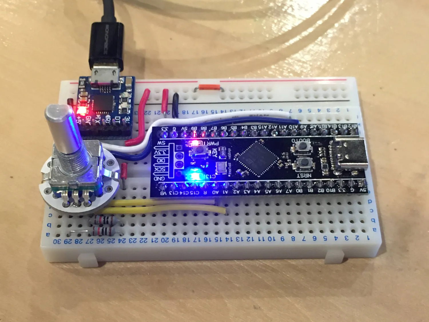
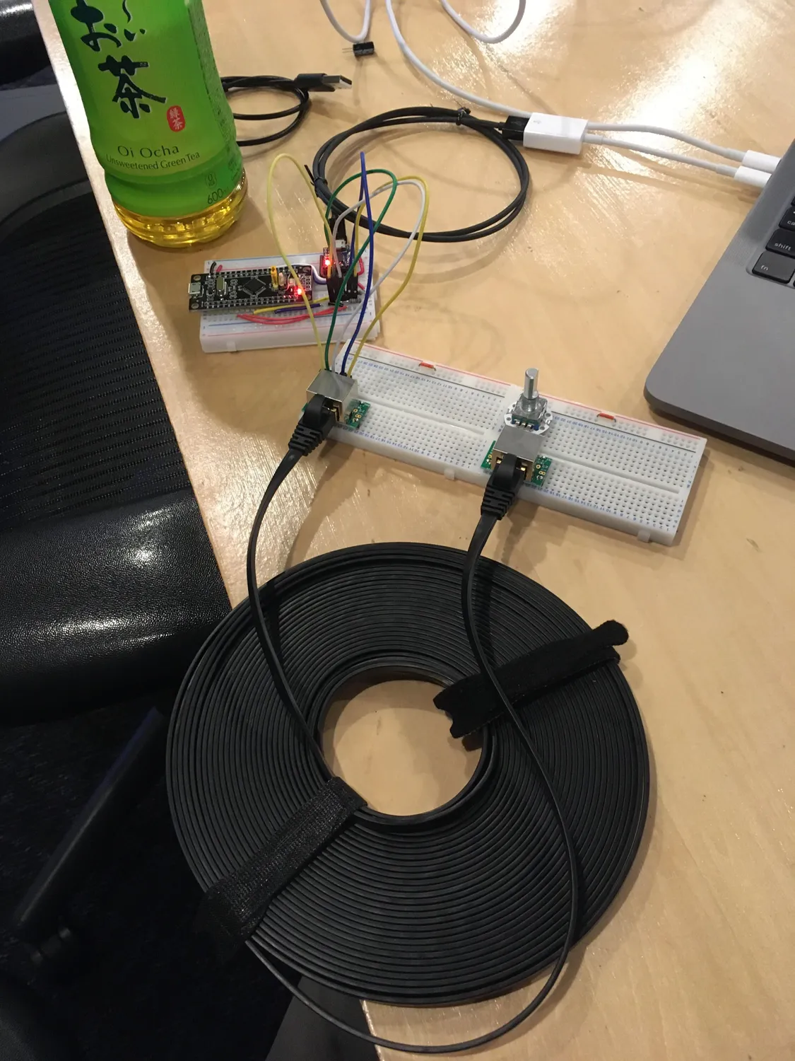
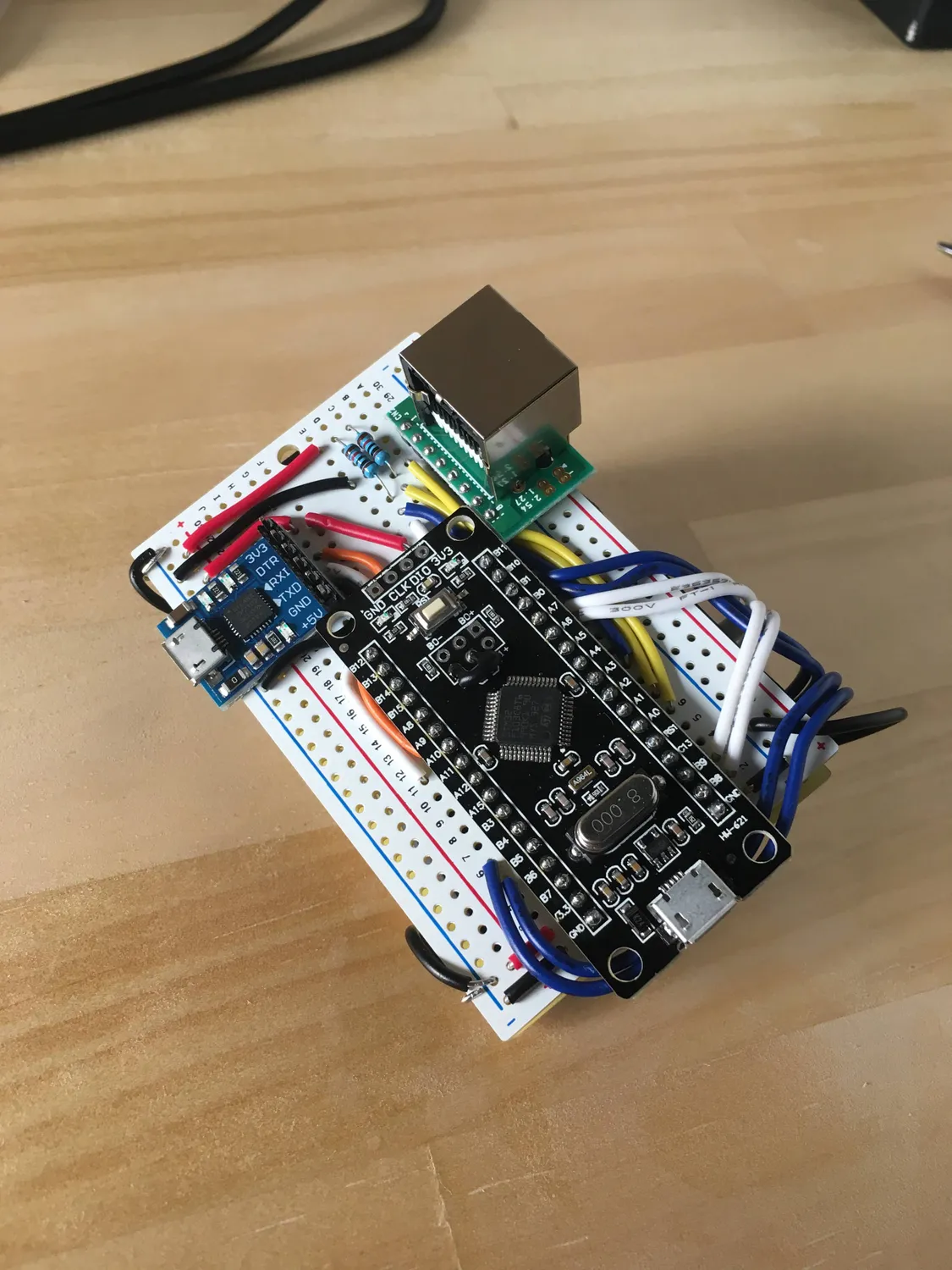
The actual hardware circuitry surrounding this embedded project was pretty straightforward to put together. We started with a breadboard and slowly added parts.
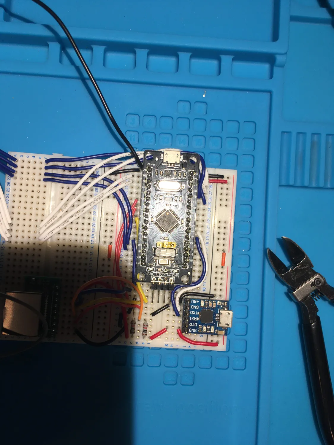
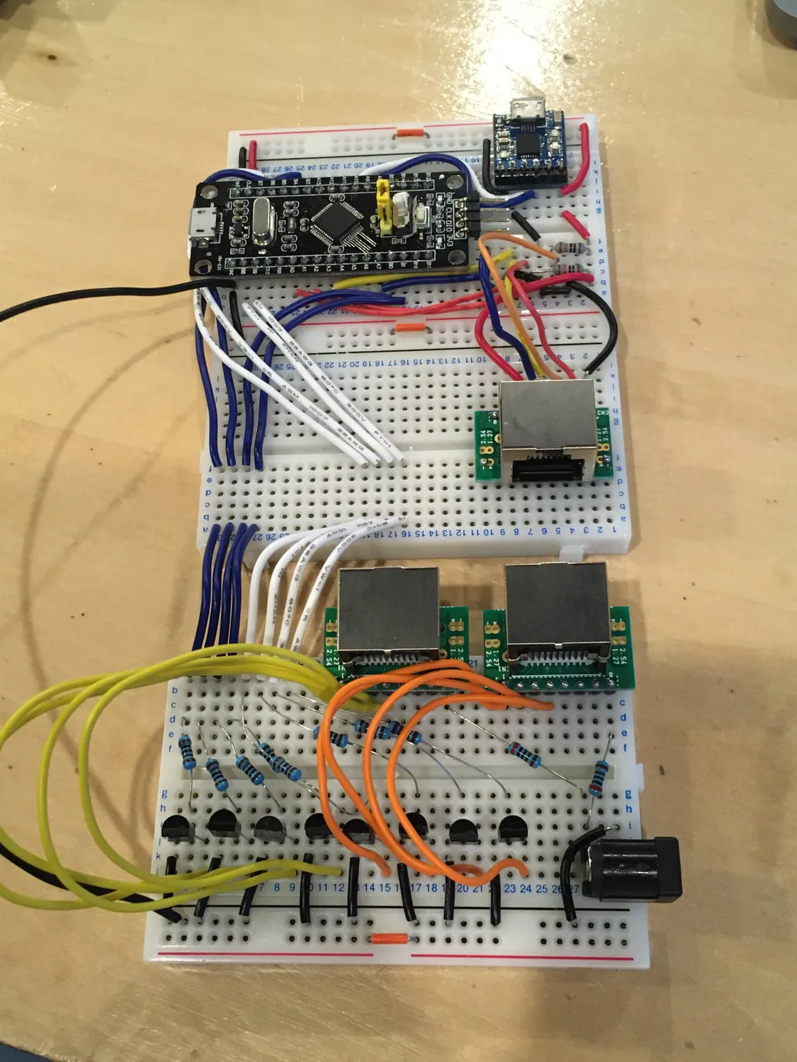
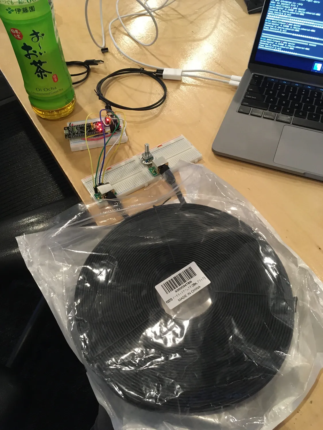
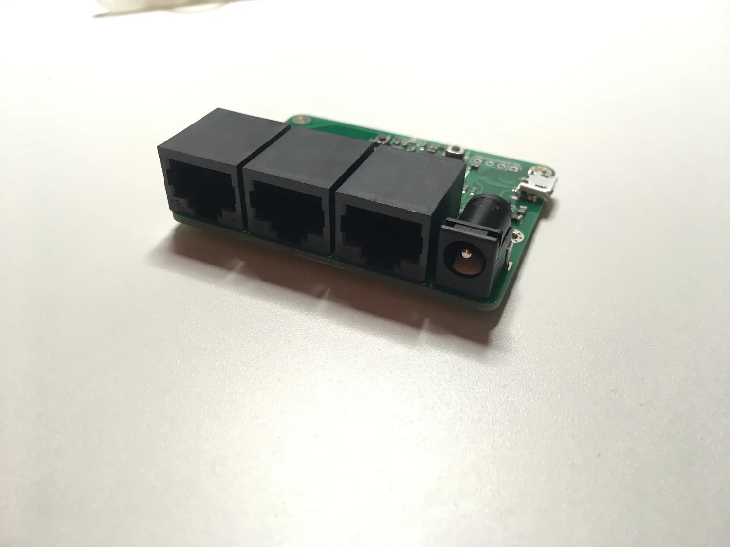
You might be wondering about the ethernet ports...we needed several signals to travel a fairly long distance since we wanted everything to be wired. Ethernet cables have 8 individual wires, are cheap to buy, and have connectors that are easy to integrate into a hardware project. I was worried there would be too much of a voltage drop or signal degradation across longer wires, but they turned out fine for our use case. I'm not an electrical engineer however, I'd love to hear from someone who is experienced if this is a Very Bad idea.
We did some tests on 20 and 30 meter cables:
After the breadboarding phase we moved the circuit to a protoboard. We decided to use protoboard which is shaped and wired up exactly the same as a typical hobbyist breadboard. This made it trivial to translate the circuit, at the expense of taking up more space and requiring a specific protoboard version (we sourced it from Akizuki Denshi).
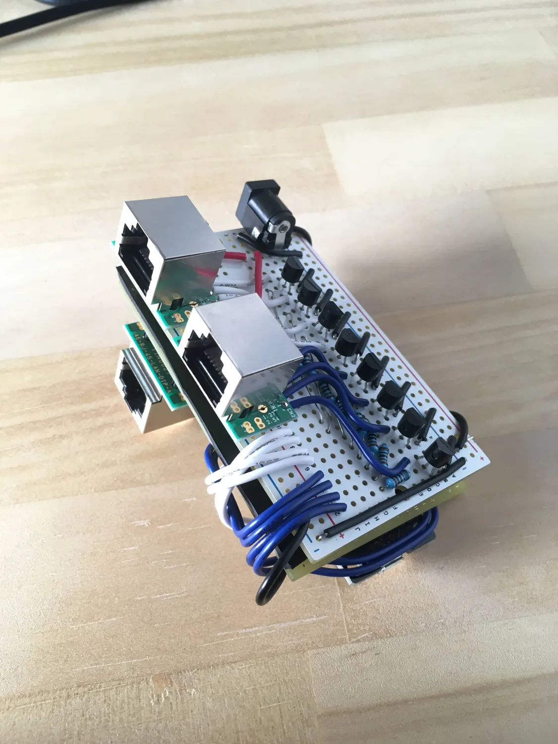
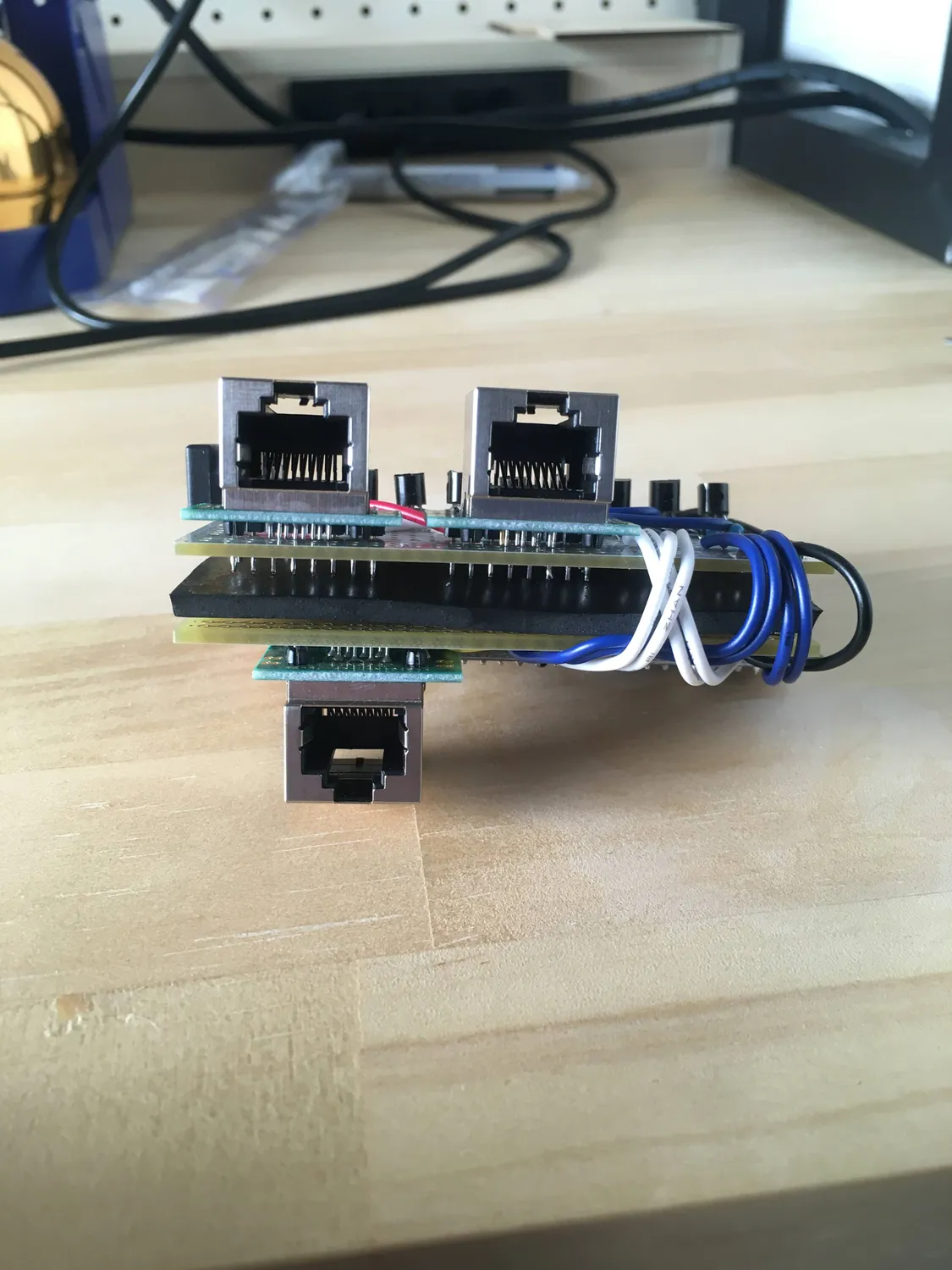
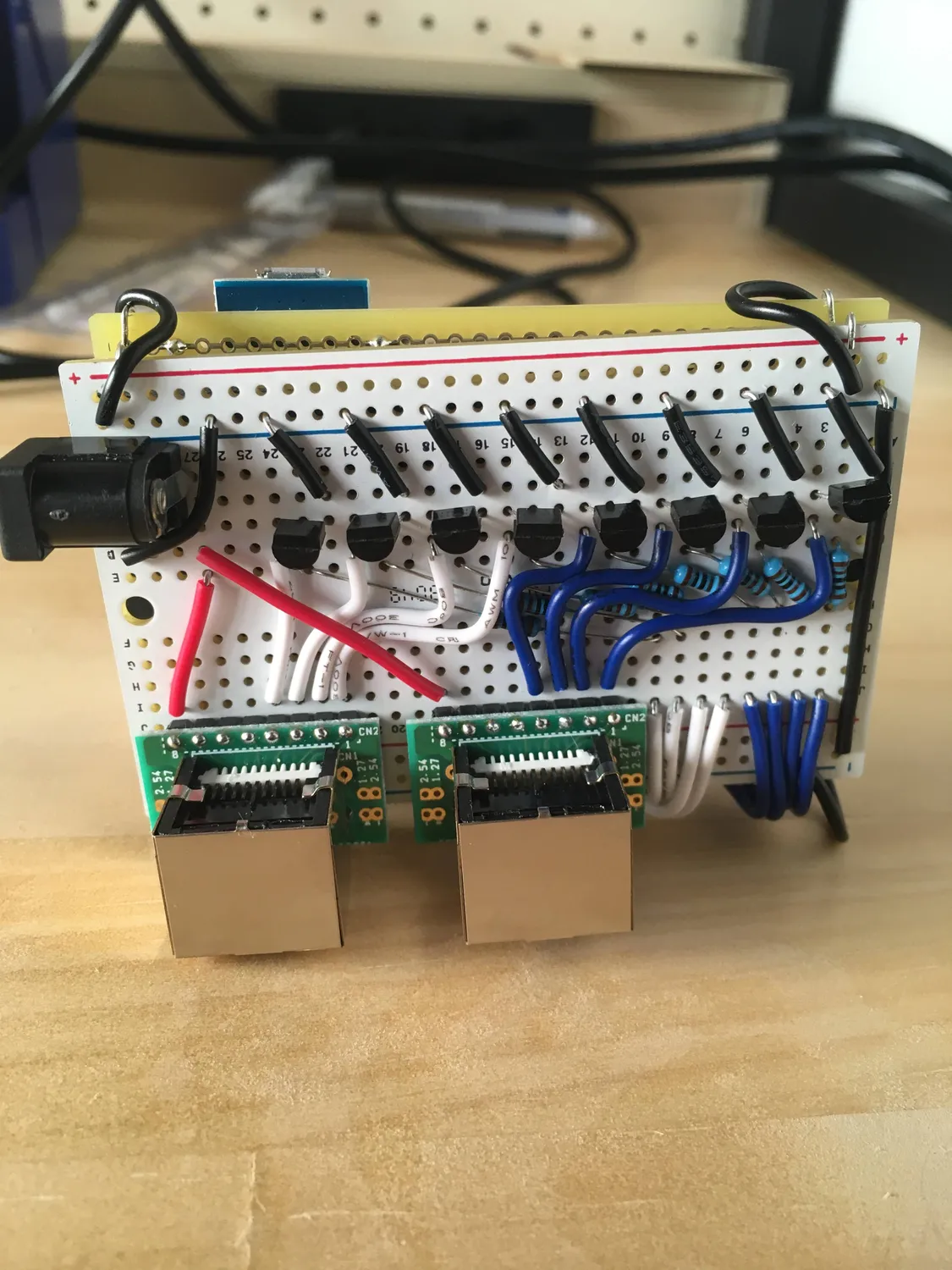
I'm looking forward to turning this circuit into a more reasonable looking PCB, as right now it's quite the monstrosity and is very time-consuming to build. But amazingly everything works and it's all powered by Rust!
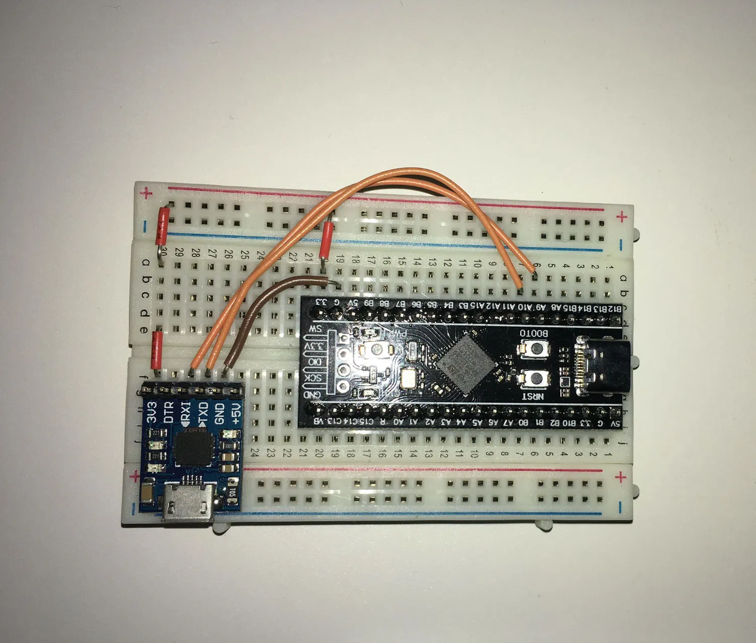
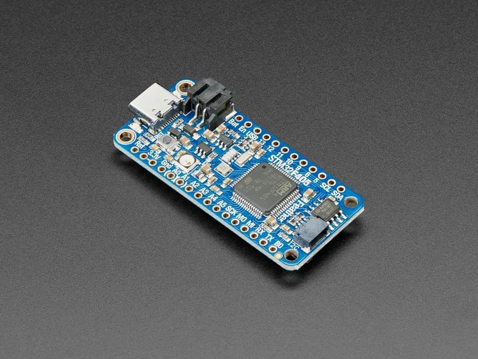
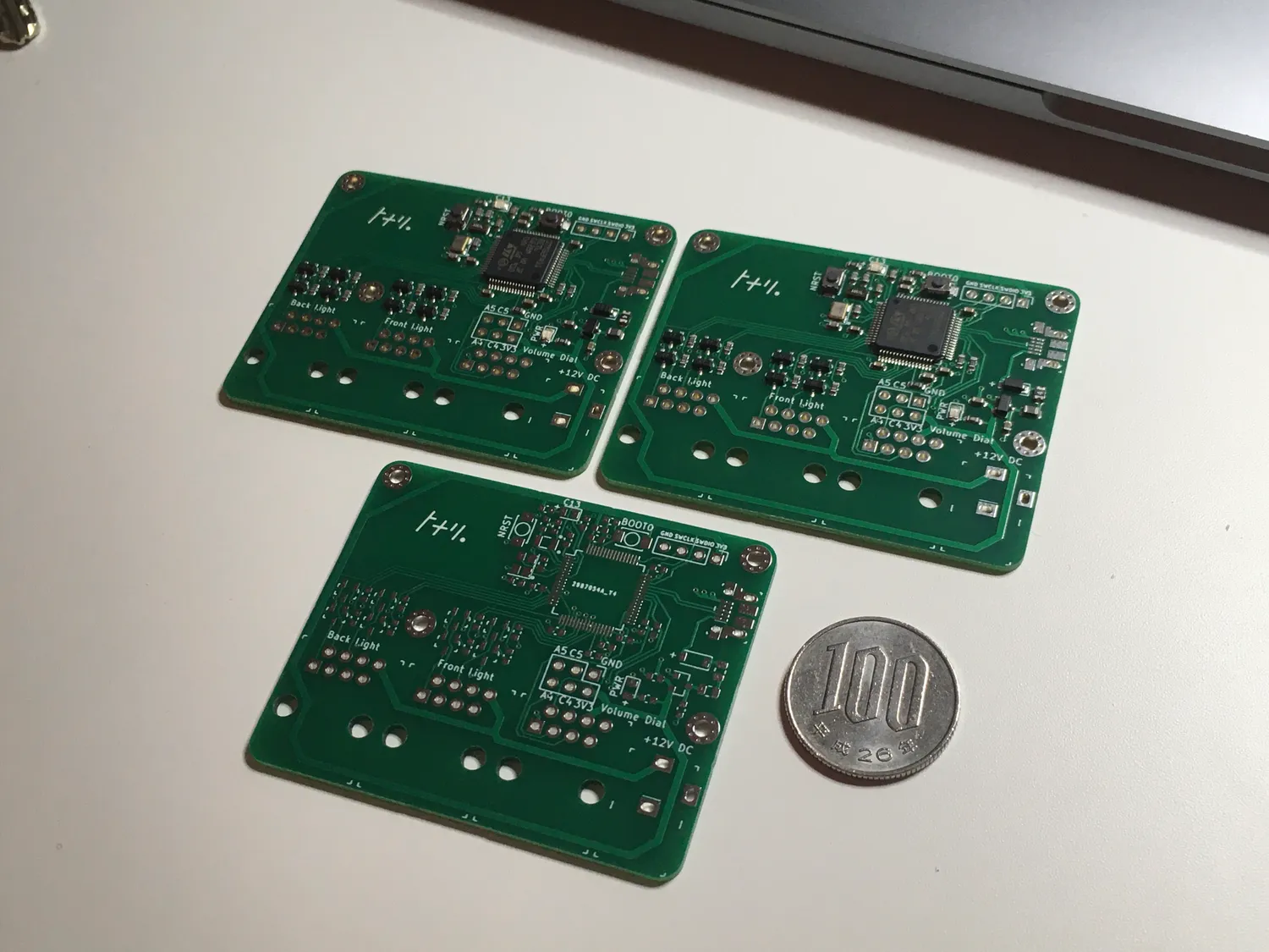
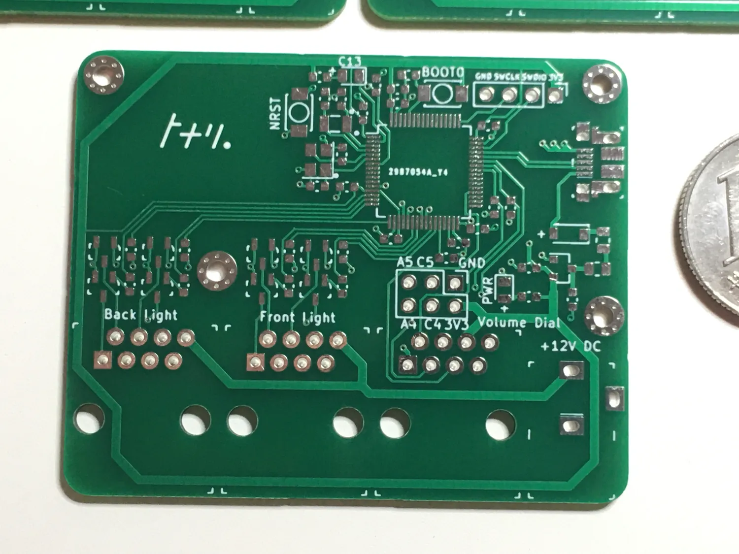
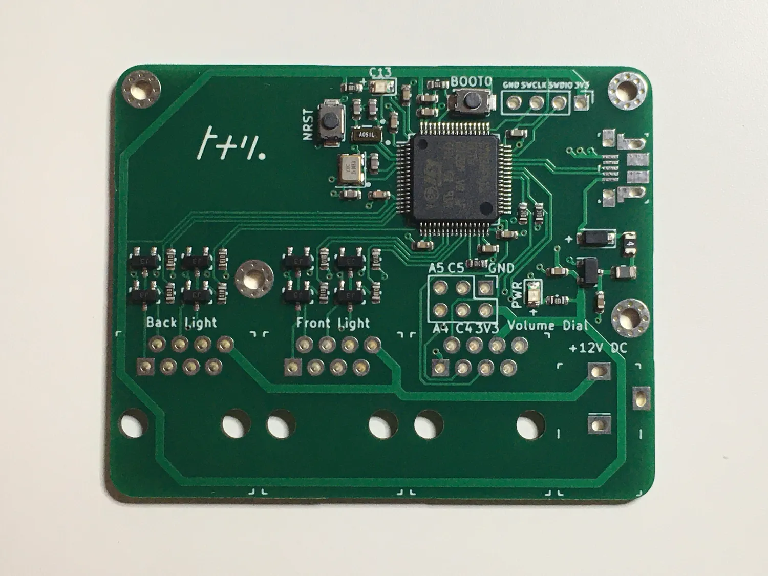
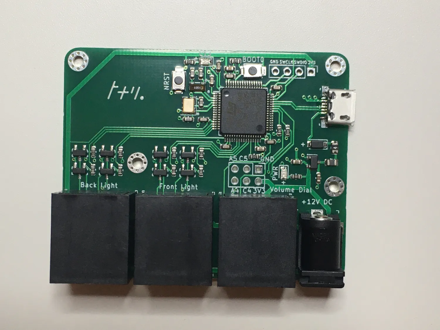
Edit: We have since designed a PCB and received the first working version! It is based on an STM32F411RE, which doesn't require a USB-serial converter for code flashing but instead can use USB DFU.
The PCB was designed in KiCAD and fabricated/assembled by JLCPCB. Special shout-out to the Phil's Lab Youtube Channel which was an immensely helpful resource for designing this board. I don't think I could have done this project without them.
I have traditionally hand-soldered all the boards I've made in the past, but having it assembled at the same shop which fabricates the PCBs was quite convenient and reasonably priced. Sadly JLCPCB doesn't offer their matte black solder mask for boards which will be assembled by them.
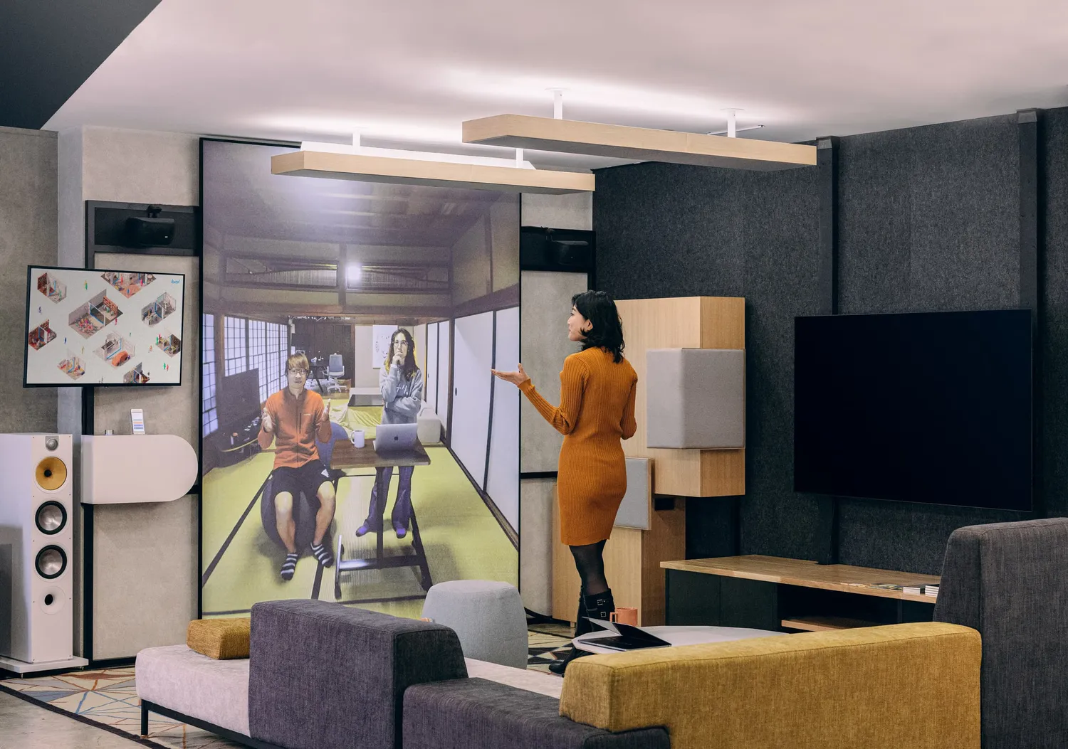
It was quite exciting to receive them, solder on a USB connector, and see it turn on and start flashing code! Here are some pictures of the end result:
End result
At the end of all this work, we now have controllable lights, an easy-to-use hardware interface for our users, and a codebase that any of our engineers can jump into and modify. For me, this experience shows incredible promise for the future of Rust in embedded systems. I wasn't expecting the implementation of this project to go as smoothly as it did. With continuing work on embedded-hal traits and drivers, support for the wildly popular ESP8266 / ESP32, and the effort being put into the development cycle, I see more and more developers being able to break into the embedded space to make their own hardware creations with speed and safety.
Again if you'd like to read the source, you can find it on github:
https://github.com/tonarino/panel-firmware
Thanks
Thanks for making it to the end, it got pretty technical but we hope you can take the information and resources from this post to start your own embedded Rust project.
If you enjoyed this and want to learn more about tonari, please visit our website and follow our progress via our monthly newsletter. And if you have questions, ideas, or words of encouragement, please don't hesitate to reach out at hey@tonari.no. 👋
Find us 💙
Facebook: @heytonari Instagram: @heytonari X: @heytonari